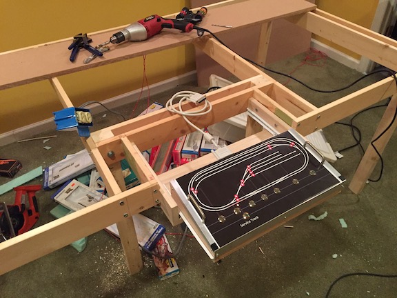
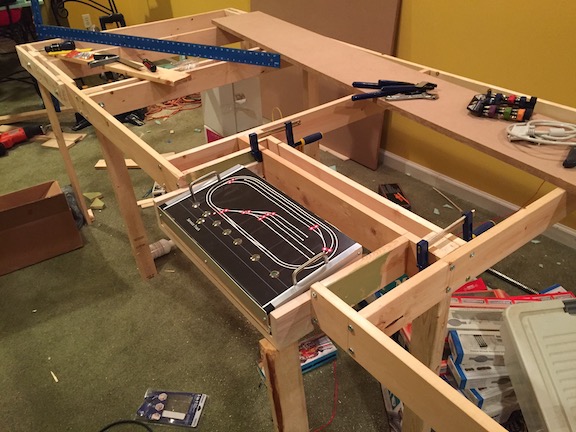
If I'd known how serious I would become, I would have developed a larger platform design. But I designed something I thought would be solid, but easy to take apart and reassemble.
I did start off with a clear idea how I would build the control console into the platform, though my notion of how the actual control panel circuitry would interconnect was less clear.
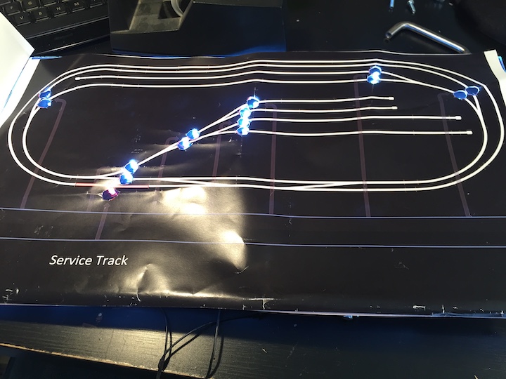
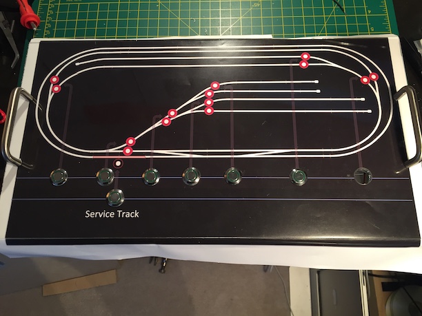
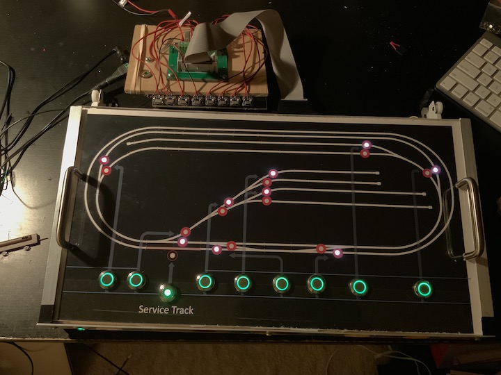
I only knew that I wanted lighted, push-button controls, and LEDs to indicator turnout positions. Little did I know, using locking DPDT switches (to route and lock the LED indicators, would require a whole shyt-load of circuitry to send continuous current to the indicator lights, while sending only a momentary charge to the turnouts, so as not to burn out the coils in the switch machines. Hey, I was a kid with big old Lionel toys the last time I dealt with this stuff!
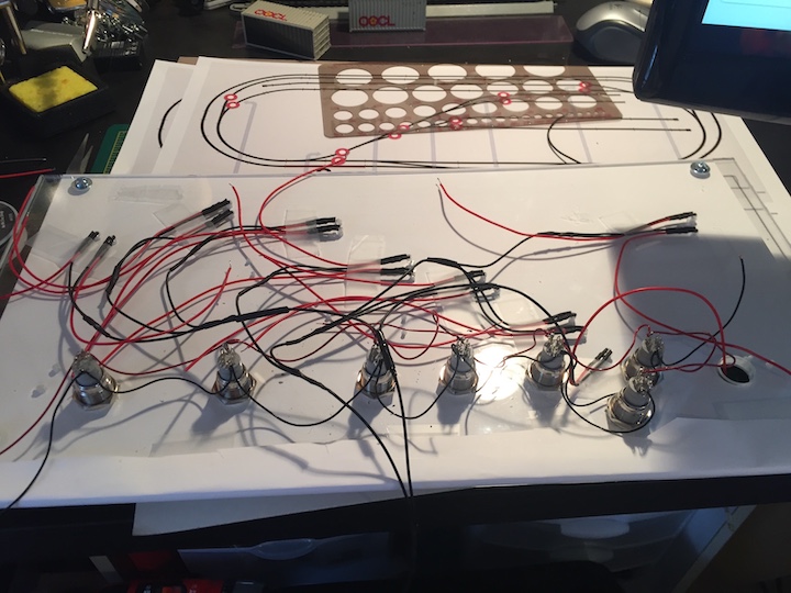
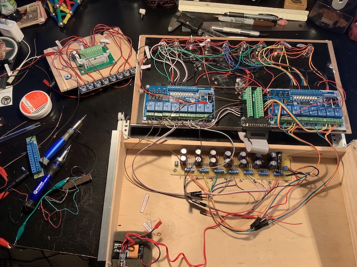
I relied on a lot of dated serial interface options to connect the console to the layout wiring. These compoments can be worked on with simple tools, are inexpensize and readily available.

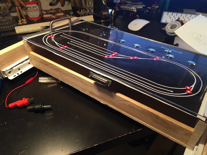
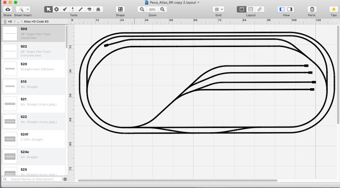
The console graphic is a pdf generated from a screen capture of the layout, generated in RailModeller Pro, the software I used to design the layout. I had 11" x 17" copies printed on 80lb. paper. One sheet served to align and drill the holes for the LEDs. Then a top sheet, with holes only for the DPTP push buttons, covers everything. The sheet underneath also keeps the LED light from bleeding outside the indicator circles onto the console.